Dr. Michael J. Scianamblo examines the envelope of motion in root canal preparation with a current review of the literature
Introduction
Schilder (1974) was the first clinician to provide a detailed discussion of the root canal preparation referring to the procedure as cleaning and shaping and to outline specific design objectives, which included a continuously tapering shape, maintenance of the original anatomy, an apex that is as small as practical, and conservation of tooth structure.
[userloggedin]
This continuously tapering space was acquired using hand instrumentation with alternating reamers and files. Each instrument was pre-curved, which dictated alternate or intermittent contact with the canal walls and created what Schilder called an “envelope of motion.” This intermittent contact not only produced continuously tapering shapes, but also minimized both the transportation of the original canal and the opportunity for instrument breakage. Close examination of Schilder’s envelope of motion reveals that although these instruments rotated axially, they cut along a precessional axis, much like a spinning top (Figure 1A).

Weine, et al., 1975, used clear acrylic blocks to evaluate the effectiveness of various instrumentation techniques, but their conclusions were somewhat disconcerting. They found that utilization of standard instruments in either reaming and/or filing produced preparations that were irregular in shape and were not continuously tapering. The narrowest part of the canal, the so-called “elbow,” was located at a point coronal to the apex or foramen. In addition, the foramen often displayed transportation, which was called the “apical zip.” These characteristics were felt to result from the elastic memory of instruments and a predilection to straighten as they are migrated around curves. To alleviate this problem, Weine suggested removing the flutes from the outer surface of pre-curved files.
Coffae and Brilliant (1976) corroborated the work of Schilder demonstrating that tapering preparations were more efficacious in the removal of debris from the root canal system when compared to parallel preparations. They also demonstrated that the serial use of files in a step-back modality were more effective in producing tapering shapes.
Abou Rass, et al., 1980, also engaged in a discussion of anti-curvature filing to minimize the problems described by Weine. This method, however, advocated the removal of conspicuous amounts of tooth structure from the outer walls of the curve of a root canal system, which arguably, would weaken the outer wall.
In another attempt to maintain the contour of the canal without transporting the apical foramen, Roane, et al., 1985, described a technique for root canal preparation called “balanced force.” The technique was a variation of reaming, which included “back-turning” the file in a counter-clockwise direction. Purportedly the restoring force or elastic memory of the file, as described by Weine, was overcome when pitted against dentinal resistance. However, Blum, Machtou, and others (1997) found that these techniques were a predisposing factor to instrument breakage.
Walia (1988) was the first experimenter to discuss the use of nickel-titanium rotary instruments in endodontics, which has changed the landscape of endodontic cavity preparation immeasurably. The earliest investigators, including Glosson, et al., 1995, and Esposito, et al., 1995, suggested that nickel-titanium rotary instruments were superior to hand instrumentation in maintaining the original anatomy and required fewer instruments. However, Schafer, et al., 1999, found that nickel-titanium instruments with traditional cross sections and sizes left all curved canals poorly cleaned and shaped, whereby tooth structure was removed almost exclusively from the outer wall of the curve. Kum, et al., 2000; Calberson, et al., 2002; and Schafer and Florek (2003) stated that the greatest failing of current NiTi designs is the continued predisposition to torsional and/or cyclic fatigue and breakage.
Nickel-titanium instruments are pre-dominately right-handed cut and with a right-handed helix. Thus, they can act like a screw as they rotate in the canal, pre-disposing them to entrapment or binding, and accompanied by cyclic fatigue and breakage (Scianamblo, 2005, and Yao, 2006).
Numerous investigators have tried to mitigate these problems. The “variable taper” system described by Maillefer (1998) and marketed as ProTaper® was specifically designed to mitigate binding. The variable taper feature has become one of the most widely used systems in the world. Cheung (2005) and Spanaki-Voredi, et al., 2006, however, demonstrated that these instruments were still subject to flexural failure and spontaneous fracture. Remarkably, in examining the earliest designs, many investigators could not find a statistically significant difference between the effectiveness of any one instrument over another (Kum, et al., 2000; Peters, et al., 2001; and Ahlquist, et al., 2001).
Heretofore, all endodontic instruments have a center of rotation and a center of mass that are identical, which dictates a linear trajectory and path of motion. Intuitively, a file design with an axis of rotation, which is coincident with the center of mass, maximizes the restoring force of the file and minimizes flexibility. And files manufactured from nickel-titanium maximizes the restoring force further. The work of Peters, et al., 2001, indicates that this restoring force prevents these instruments from contacting the entire anatomy of the root canal preparation, leaving as much as 35% of the internal anatomy of the canal untouched, and the preparation poorly centered and unclean.
In evaluating these problems, it became clear that a review of Herbert Schilder’s requirements for an ideal endodontic cavity preparation would be necessary to design a new file. Ideally a design that would mimic Schilder’s envelope of motion would mitigate these problems.
Again referring to Figure 1A, it becomes apparent that Schilder’s envelope of motion was created using a unique method of manipulating the root canal file, whereby each pre-curved instrument that revolved within the canal walls could only cut in the greatest portion of the curve. Thus, as each instrument was inserted into deepest portion of the canal, although the rotation was around a central axis, the cutting itself was occurring around a precessional axis.
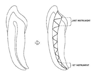
As an example, Figure 1B demonstrates how a series of seven successively larger instruments could be used to expand the cutting envelope, but again notice that cutting is done intermittently and along a precessional axis or via mechanical waves. Our objective, then, was the development of new method of canal enlargement that would mimic this concept.

Although this idea was conceptual (Figure 2), the machine tool capabilities of Maillefer Dental Products or Dentsply International (Ballaigues, Switzerland) made this concept a reality. More than a dozen prototypes were engineered and tested over an 8-year period, which led to the development of what was originally called “swaggering files,” now called X-files and embodied in the ProTaper NEXT™ design. In referring to Figure 2, it can seen that the cutting edges of the file are oriented such that they cut in the perimeter of the cutting envelope or precessionally, enabling intermittent cutting. It can also be seen how a design like this might mitigate binding and the predisposition for breakage, while improving hauling or debris removal.
Performance
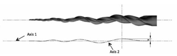
ProTaper NEXT was designed to mimic Schilder’s envelope of motion by offsetting a rectilinear cross section, which revolves (6-7 revolutions) around the central axis. These revolutions are also called pitch. In Figure 3, the central or rotational axis of the X-file is shown by Axis 1. Axis 2 follows the center of mass or geometric center of the X-file. The amount of offset between the center of rotation and the center of mass is defined by the distance between these two axes and varies along the length of the file or distance X.
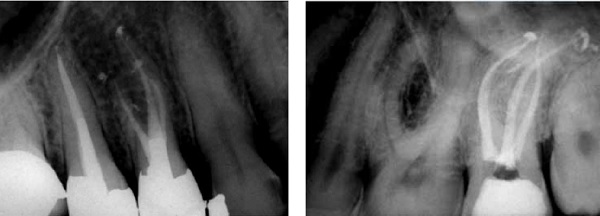

When observed during operation, precession of the X-file gives the appearance of a traveling wave (Scianamblo, 2005, 2006, 2011, and 2015). What is essential to the design of the X-file is that the un-dulating nodes and precessional axis of the X-file circumscribes an envelope of motion similar to Schilder’s pre-curved file (Figure 1A). What is also essential to the design of the X-file is that the offset cross section mitigates the restoring force, similar to Roane’s balanced force technique, which should improve centering. This is dictated by Newton’s laws for the mass moment of inertia and the parallel-axis theorem. Simply stated, the resistance to bending and distortion of a given lamina or cross section can be increased or decreased exponentially, as the distance of the centroid (center of mass) from the central axis is varied. The testing of the X-files has demonstrated that offsetting the center of mass produces not only efficient cutting instruments, but also instruments that remained exceptionally well centered, minimizing transportation (Pasqualini, et al., 2015; Burklein, et al., 2015; Saber, et al., 2015; Zhao, et al., 2104; and Elnaghy, et al., 2014) and corroborated clinically (Figures 4, 5, 8, and 9).

Figure 9: A postoperative radiograph of an upper second bicuspid with severely dilacerated canals and a complex bend. The mesial canal was prepared with files X1 and X2 only. The palatal canal was prepared with X1, X2, and X3. The canals were obturated using Schilder technique (X. Brant, Belo Horizonte, Brazil)
For further analysis, we will define each arc as a wave of amplitude X as shown in Figure 6. The total distance traveled by any point on the arc can then equal 2X, which defines the cut diameter. Thus, the cutting envelope associated with any node along the instrument’s profile is potentially twice as wide as the instrument at that cross section.
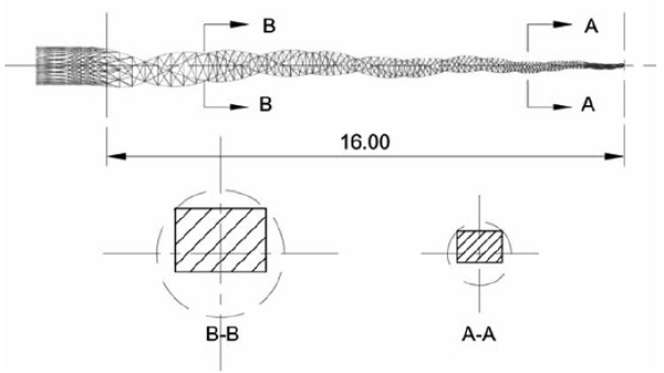
As mentioned, this file design (Figures 2 and 7) features an offset rectilinear cross section. As can be seen from this figure, only two cutting angles engage the walls of the root canal at any one time. This offset rectilinear cross section not only contributes to the innate flexibility of the file, but also permits intermittent cutting, which mitigates cyclic fatigue (Perrez-Higueras, et al., 2014; Nyguen, et al., 2014, and Elnaghy, et al., 2014). In addition, the offset cross section provides larger clearance angles for hauling, which can further enhancing the cutting efficiency and performance, and mitigate the opportunity for apical extrusion of debris (Capar, et al., 2014 and Kocak 2015).
Lastly, the helical architecture of the file would imply that the instruments are compressible. Although these studies are not complete, it has been demonstrated that these instruments impart less internal stress and can minimizing crack formation (Capar, et al., 2014; Arias, et al., 2014; and Berutti, 2014), in addition to cutting more efficiently (Burkelin, et al., 2014, and Pasqualini, et al., 2014).
In light of this current research and reports of clinical success, this offset feature has been incorporated into the next generation of reciprocating files recently introduced as WaveOne® Gold. Continued research will be required to elaborate other advantages of ProTaper Next and similar designs.
Sequence and method of use
Again referring to Figure 3 and as stated previously, the instruments create larger cutting envelopes utilizing smaller cross sections. Thus, canals can be prepared safely with only two or three instruments. The clinical guidelines for use of ProTaper Next instruments was discussed previously by Van der Vyver and Scianamblo (2013 and 2014). In summary, a torque-controlled handpiece should be set at 300 rpms and 2NCm. Use up to 4 NCm may be considered as experience dictates.
The X-file sequence is preceded by creation of a glide path with a No. 10 file, followed by the use of the PathFiles, or similar glide path files, e.g., ProGlider or a number 15-K file. Further enlargement of the upper portion of the canal and removal of restrictive dentin can also be accomplished using the XA orifice opener or use of the X1 in the coronal portion of the canal only.
Once the glide path has been established, the X-File sequence using X-1 and X-2 is carried to the working length using a pull-pull motion allowing the instrument to work without forcible pressure in a continuous push-pull movement. Brushing may also be used to remove restrictive dentin due to the precessional cutting feature of these files. The instruments should be used in the presence of NaOCL and, as with all rotary nickel-titanium instruments, irrigation and recapitulation should follow the use of each instrument.
The narrowest canals can usually be prepared with only the X1 (17/04) and X2 (25/06). Larger canals can be prepared by adding the X3 (30/07). The X4 (40/06) and X5 (50/06) can be used for much larger canals or enlargement vehicles in the upper portion of the canal, if a greater taper is desired. Finally, gauging should be accomplished using the hand file that corresponds to the tip size of each X-file.
[/userloggedin]
[userloggedout][/userloggedout]
- Ahlquist M, Henningsson O, Hultenby K, and Ohlin J. The effectiveness of manual and rotary techniques in the cleaning of root canals: a scanning electron microscopy study. Int Endod J. 2001;34(7):533-537.
- Arias A, Singh R, and Peters OA. Torque and force Induced by ProTaper Universal and ProTaper Next during shaping of large and small root canals in extracted teeth. J Endod. 2014;40(7): 973–976.
- Berutti, E, Alovisi, M, Pastorelli, MA, Chiandussi, G, Scotti, N and Pasqualini, D. Energy consumption of ProTaper Next X1 after glide path with PathFiles and ProGlider. J Endod. 2014; 40(12): 2015-2018.
- Blum JY, Machtou, P, Esber S, Micallef, JP. Analysis of forces developed during root canal preparation with the balanced force technique. Int Endod J. 1997;30(6):386-396.
- Bürklein S, Mathey D, Schäfer E. Shaping ability of ProTaper NEXT and BT-RaCe nickel-titanium instruments in severely curved root canals. Int Endod J. 2015;48(8): 774-781.
- Berutti E, Alovisi M, Pastorelli MA, Chiandussi G, Scotti N, Pasqualini D. Energy consumption of ProTaper Next X1 after glide path with PathFiles and ProGlider. J Endod. 2014; 40(12):2015–2018.
- Calberson FL, Deroose CA, Hommez GM, Raes H, De Moor RJ. Shaping ability of GT Rotary Files in simulated resin root canals. Int J Endod. 2002;35(7):607-614.
- Capar ID, Arslan H, Akcay M and Uysal B: Effects of ProTaper Universal, ProTaper Next, and HyFlex instruments on crack formation in dentin. J Endod. 2014;40(9):1482–1484.
- Capar ID, Arslan H, Akcay M, Ertas H. An in vitro comparison of apically extruded debris and instrumentation times with ProTaper Universal, ProTaper Next, Twisted File Adaptive, and HyFlex instruments. J Endod. 2014;40(10):1638–1641.
- Cheung GS, Peng B, Bian Z, Shen Y, Darvell BW. Defects in ProTaper S1 instruments after clinical use: fractographic examination. Int Endod J. 2005;38(11):802-809.
- Chow DY, Stover SE, Bahcall JK, Jaunberzins A, Toth JM. An in vitro comparison of the rake angles between K3 and ProFile endodontic file systems. J Endod. 2005;31(3):180-182.
- Coffae KP, Brilliant JD. The effect of serial preparation versus nonserial preparation on tissue removal in the root canals of extracted mandibular human molars. J Endod. 1975;1(6):211-214.
- Elnaghy AM and Elsaka, SE: Assessment of the mechanical properties of ProTaper Next nickel-titanium rotary files J Endod. 2014; 40:1830–183.
- Elnaghy AM, Elsaka SE. Evaluation of root canal transportation, centering ratio, and remaining dentin thickness associated with ProTaper Next instruments with and without glide path. J Endod. 2014;40(12):2053–2056.
- Esposito, PT, Cunningham, CJ. A comparison of canal preparation with nickel-titanium and stainless steel instruments. J Endod. 1995;21(4):173-176.
- Glosson CR, Haller RH, Dove SB, Del Rio CE. A comparison of root canal preparations using N-Ti hand, Ni-Ti engine-driven and K-flex endodontic instruments. J Endod. 21(3):146-151.
- Koçak MM, Çiçek E, Koçak S, Sağlam BC, Yılmaz N. Apical extrusion of debris using ProTaper Universal and ProTaper Next rotary systems. Int Endod J. 2015;48(3):283-286.
- Kum KY, Spängberg L, Cha BY, Il-Young J, Msd, Seung-Jong L, Chan-Young L. Shaping ability of three ProFile rotary instrumentation techniques in simulated resin root canals. J Endod. 2000;26(12):719-723.
- Maillefer, PL, Aeby, F, inventors; Maillefer Instruments, S.A. Instrument for boring dental radicular canals. US Patent 5,746,597. May 5, 1998.
- Pérez-Higueras JJ, Arias A, de la Macorra JC, Peters OA. Differences in cyclic fatigue resistance between ProTaper Next and ProTaper Universal instruments at different levels. J Endod. 2014;40(9):1477–1481.
- Nguyen HH, Fong H, Paranjpe A, Flake NM, Johnson JD, Peters OA. Evaluation of the resistance to cyclic fatigue among ProTaper Next, ProTaper Universal, and Vortex Blue rotary instruments. J Endod. 2014;40(8):1190–1193.
- Pasqualini D, Alovisi M, Cemenasco A, Mancini L, Paolino DS, Bianchi CC, Roggia A, Scotti N, Berutti E. Micro–computed tomography evaluation of Protaper Next and BioRace shaping outcomes in maxillary first molar curved canals. J Endod. 2015; 41(10):1706-1710.
- Peters OA, Schönenberger K, Laib A. Effects of four Ni-Ti preparation techniques on root canal geometry assessed by micro computed tomography. Int Endo J. 2001;34(3):221-230.
- Roane JB, Sabala CL, Duncanson MG Jr. The “balanced force” concept for instrumentation of curved canals. J Endod. 1985;11(5):203-211.
- Scianamblo, MJ. A contemporary approach to cleaning and shaping the root canal system emphasizing “early coronal enlargement.” In: Castellucci A. Endodontics. Chapter 16. Florence, Italy: Il Tridente. 2005:470-501.
- Scianamblo, MJ, inventor. Critical path endodontic instruments for preparing endodontic cavity spaces. US Patent 6,942,484. Sept 13, 2005.
- Scianamblo, MJ, inventor. Bending endodontic instruments. EP Patent 1,709,934 B1. March 30, 2011.
- Scianamblo, MJ, inventor. Endodontic instruments for preparing endodontic cavity spaces. US Patent 7,955,078. June 7, 2011.
- Scianamblo, MJ, inventor. Swaggering Endodontic Instruments. US Patent 8,454,361. June 4, 2013.
- Scianamblo, MJ, inventor. Swaggering Endodontic instruments. US Patent 20150173853. June 25, 2015.
- Spanaki-Voreadi AP, Kerezoudis NP, Zinelis S. Failure mechanism of ProTaper Ni-Ti rotary instruments during clinical use: fractographic analysis. Int Endod J. 2006; 39(3):171-178.
- Schäfer, E. Relationship between design features of endodontic instruments and their properties. Part 2. Instrumentation of curved canals. J Endod. 1999; 25(1):56-59.
- Schäfer E, Florek H. Efficiency of rotary nickel-titanium K3 instruments compared with stainless steel hand K-Flexofile. Part 1. Shaping ability in simulated curved canals. Int Endo J. 2003; 36(3):199-207.
- Schilder H. Cleaning and shaping the root canal. Dent Clin North Am. 1974;18(2):269-296.
- Walia HM, Brantley WA, Gerstein H. An initial investigation of the bending and torsional properties of Nitinol root canal files. J Endod. 1988;14(7):346-351.
- Weine FS, Kelly RF, Lio PJ. The effect of preparation procedures on original canal shape and on apical formation shape. J Endod. 1975;1(8):255-262.
- Yao JH, Schwartz SA, Beeson TJ. Cyclic fatigue of three types of rotary nickel-titanium files in a dynamic model. J Endod. 2006;32(1):55–57.
Stay Relevant With Endodontic Practice US
Join our email list for CE courses and webinars, articles and more..